

This article provides an overview of "Metastability", "Clock Domains", the hazards associated with them and finally the mitigation techniques.
Clock Domain
Part of the design that is driven by one or more clocks that are related to each other. For example if a design is fed two clocks, 100 MHz and divided by two (50 MHz) of the same 100 MHz clock is considered as single clock domain. However, a design has multiple clock domains if it is fed by two or more clocks that are not related to each other.
Data Sharing
In the day to day FPGA development, there comes a need to share the data between different clock domains. The sharing process is very simple if the design has only single clock domain. However in case of data sharing between multiple clock domains, a special care should be taken i.e. Clock Domain Crossing (CDC).
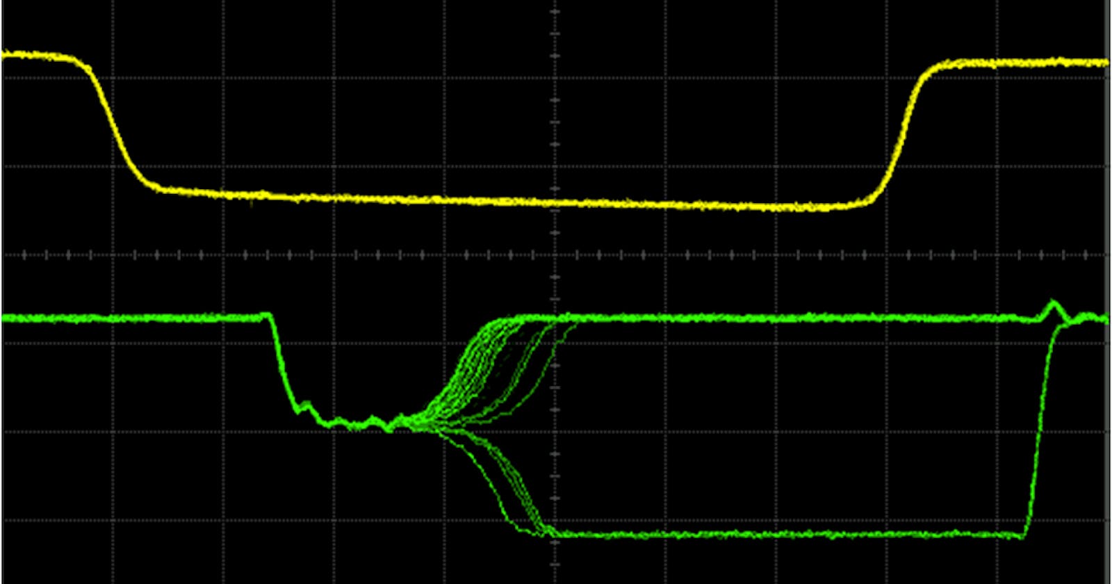
Metastability
In very simple term metastability is basically a intermediate or unstable state. If the signal is shared between different clock domains without CDC then there are chances metastability i.e. a state where signal has not to settled to either '1' or '0'.
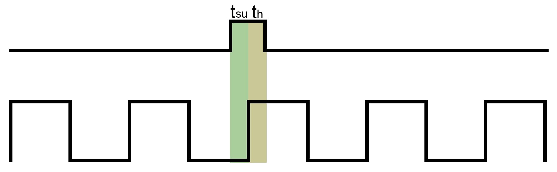
Setup Time
The time for which the input must be stable before the triggering-edge of the clock. If data is changing within this setup time window, the input data might be lost and not stored in the flip-flop as metastability might occur.
Hold Time
The time for which the input must be stable after the triggering-edge of the clock. Similar to the setup time, hold time violation can also cause the loss of data or metastability.
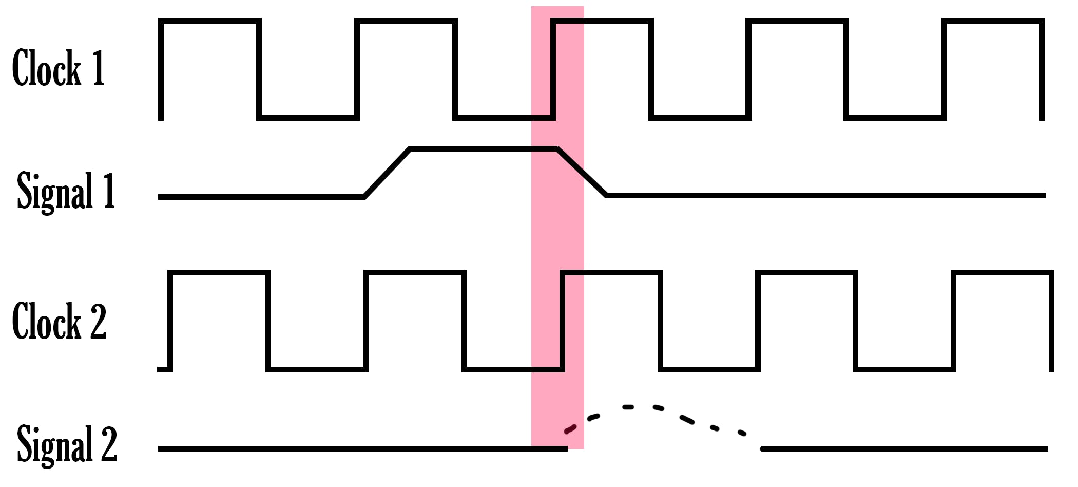
The following figure demonstrates the metastability caused by the violation of setup and hold timings. Here Clock 1 and Clock 2 are not inter related and signal 1 and signal 2 are generated from their corresponding clock domains. When the data is shared between the two clock domains, metastability occurs (red bar).
Metastability occurrence of a Flip Flop can be predicted by using MTBF (Mean Time Between Failure) and is measured in years. It is possible to calculate MTBF given the data rate at the input and the clock frequency of the Flip Flop.
So the lesson learnt is that in a digital system, for the proper operation, the design must meet the setup, hold timings with proper handling of metastability.
Latching a meta-stable signal can cause entire designs to come to halt. Metastability can cause activating wrong data paths or take the design to invalid states as well, hence the output becomes unpredictable.
Clock Domain Crossing
The process of passing a signal or vector from one clock domain to another clock domain is called as CDC. CDC must be handled for safe sharing of data between multiple clock domains.
Following are few of the techniques used for CDC
- multi Flip Flop (m-FF) based synchronizers - NOTE: Only for single bit data sharing
- MUX based synchronizers
- Handshake signals
- FIFO memories
- Toggle synchronizers
- Vendor specific CDC tools
We will go through each of them in detail in the next articles of the FPGA series.
Feel free to reach out:
LinkedIn: linkedin.com/in/muhammad-hamza-muneer-39663..
e-Mail: hamzamuneer95@yahoo.com